Loop Antenna Radiation Pattern
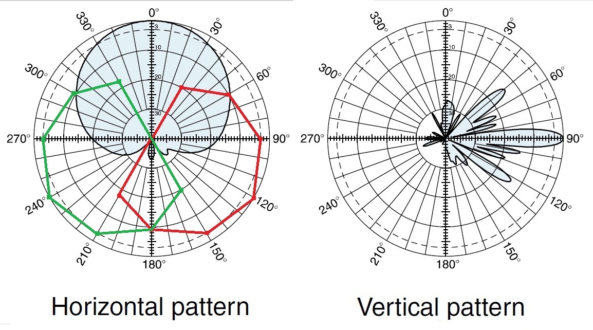
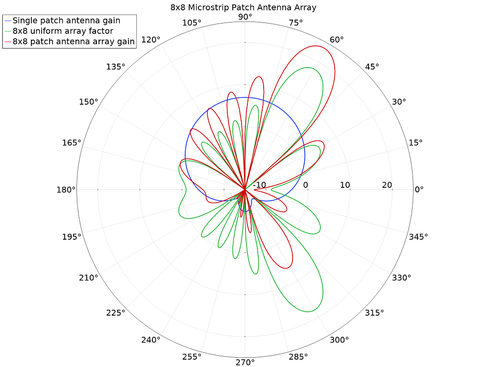
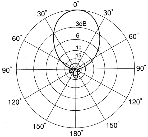
Loop Antenna Radiation Pattern - Web theory of large loop antennas. Web b the calculated and simulated radiation patterns for the loop antenna models at 2.45 ghz. In the second part of this antenna basics series, you will learn more about the physics of how antennas work. These antennas have low radiation resistance and high inductive reactance, so that their impedance is difficult to match to a radio impedance (often 50 ohms). October 12, 2016 by mark hughes. A novel reconfiguration scheme is adopted that only switches the phase of the electric dipole by 180° in an electrically small huygens (complementary) source. The radiation patterns for different angles of looping are also illustrated clearly in the figure. To have a better understanding, consider the following figure, which represents the radiation pattern of a dipole antenna. 2 the azimuthal radiation or reception pattern for the ideal small loop antenna is shown in fig. Web an antenna is a device that couples currents to electromagnetic waves for purposes of radiation or reception. Larger loops, 2 wavelengths or more, which have maximum radiation off the sides of the loop, and may have a broadside null. In the second part of this antenna basics series, you will learn more about the physics of how antennas work. A circular loop of constant current. These antennas have low radiation resistance and high inductive reactance, so that. Dipole antenna (l = 2λ) magnitude/ amplitude. This horizontal loop (or “sky loop”) was developed for use on field day, with a specific site and radiation pattern in mind. Loop antennas (radiation parameters of a small loop. Web the antenna feed points would be in series with the loop, such that a small loop looks somewhat like a short circuit. This chapter on loop antennas covers implementation aspects of both electrically small and electrically large loops which have a wide range of applications. Dipole antenna (l = 2λ) magnitude/ amplitude. Web a radiation pattern defines the variation of the power radiated by an antenna as a function of the direction away from the antenna. The increase in the perimeter or. Half wave dipole antenna (l=0.5 λ) current distribution. Here, c denotes the loop’s circumference. Radiation patterns, permittivity, directivity, and gain. This is probably the most common loop for ham radio use. A novel reconfiguration scheme is adopted that only switches the phase of the electric dipole by 180° in an electrically small huygens (complementary) source. This is probably the most common loop for ham radio use. 2 the azimuthal radiation or reception pattern for the ideal small loop antenna is shown in fig. This horizontal loop (or “sky loop”) was developed for use on field day, with a specific site and radiation pattern in mind. Web b the calculated and simulated radiation patterns for the. The increase in the perimeter or the number of turns in the loop electrically enhance the radiation resistance of the loop. 2 the azimuthal radiation or reception pattern for the ideal small loop antenna is shown in fig. Dipole antenna (l = 2λ) magnitude/ amplitude. October 12, 2016 by mark hughes. In the representation of radiation pattern, we often come. Web a radiation pattern defines the variation of the power radiated by an antenna as a function of the direction away from the antenna. With larger loops (in terms of wavelengths), the patterns can have multiple lobes and nulls. Web the radiation pattern of a transmitting antenna describes the magnitude and polarization of the field radiated by the antenna as. Ferrite loops.) introduction loop antennas form another antenna type, which features simplicity, low cost and versatility. In the second part of this antenna basics series, you will learn more about the physics of how antennas work. Web loop antennas are usually classified as electrically small ( c < λ / 3 ) and electrically large (c ∼ λ ). Web. Web b the calculated and simulated radiation patterns for the loop antenna models at 2.45 ghz. In the case of large loop antennas, the field pattern is such that the null is in the direction of the antenna axis. The top shows the directive pattern of a horn antenna, the bottom shows the omnidirectional pattern of a simple vertical dipole. Last updated 28 november 2023. Radiation patterns, permittivity, directivity, and gain. Half wave dipole antenna (l=0.5 λ) current distribution. Loop antennas can have various Antennas allow information to be transferred to distant locations. Web azimuth radiation pattern of a horizontally polarized full wave loop antenna in free space. A pattern may also be defined for a receiving antenna, however, we defer discussion of the receive case to a later section. Web a half wave antenna fits one positive or negative part of the wave. The small loop as a receiving antenna. Web full wave loops, (generally between 2/3 and 3/2 wavelengths) which have maximum radiation broadside to the loop. 2 the azimuthal radiation or reception pattern for the ideal small loop antenna is shown in fig. In the second part of this antenna basics series, you will learn more about the physics of how antennas work. Web b the calculated and simulated radiation patterns for the loop antenna models at 2.45 ghz. Web radiation pattern as function of polar angle, for different azimuthal angles. Web an antenna is a device that couples currents to electromagnetic waves for purposes of radiation or reception. That makes the radiation pattern weird. Dipole antenna (l = 2λ) magnitude/ amplitude. Larger loops, 2 wavelengths or more, which have maximum radiation off the sides of the loop, and may have a broadside null. Radiation patterns, permittivity, directivity, and gain. Equivalent circuit of the loop antenna. In the case of large loop antennas, the field pattern is such that the null is in the direction of the antenna axis.
Radiation pattern plot of the loop antenna. Download

Antenna Radiation Pattern and Antenna Tilt RAYmaps

Omnidirectional Antenna Radiation Pattern

Omnidirectional Antenna Radiation Pattern

RadiationPatternLoopAntenna IoT M2M blog

How to Synthesize the Radiation Pattern of an Antenna Array COMSOL Blog

Omnidirectional Antenna Radiation Patterns Explained MP Antenna

14 Radiation Pattern of Small and Large Loop Antenna Download

Loop Antenna Radiation Pattern

Simulated radiation patterns of the reference rectangular loop antenna
Web Loop Antennas Are Usually Classified As Electrically Small ( C < Λ / 3 ) And Electrically Large (C ∼ Λ ).
Courtesy Himanshu Rohilla, 3Rd Year Ee, Iit Delhi.
This Is Probably The Most Common Loop For Ham Radio Use.
Web The Antenna Feed Points Would Be In Series With The Loop, Such That A Small Loop Looks Somewhat Like A Short Circuit Across The Antenna Feed.
Related Post: