Hole Pattern As Datum
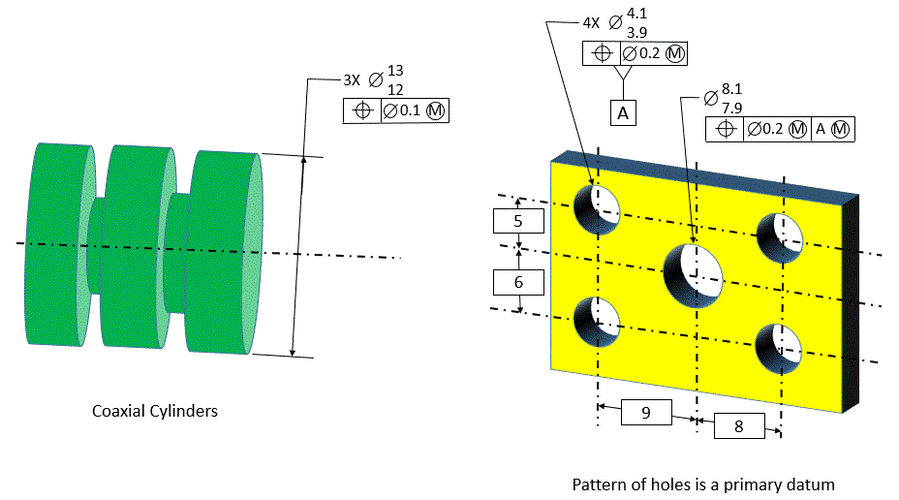
Hole Pattern As Datum - The drawing below (figure 2), depicts design intent. Web your first plane is on the face coincident with datum feature a, the 12mm hole creates an axis which is at the intersection of the second and third plane. This is an unusual situation, but it is possible. Web the size dimension that the datum feature symbol is associated with is for the pattern of holes, therefore the pattern of holes is the datum feature. The large hole in the middle of the part is then located relative to the pattern of four holes. After rethinking, individually won't be needed, as the datum feature symbol will have a direct leader to a specific. The tolerance of position locates the holes within the pattern relative to each other. Web a datum reference symbol is typically attached to the diameter dimension of the holes in a pattern. From either end of the bush and average it or insert a shaft thru the hole take dimension on the shaft near the assembly datum and arrive. Web the 4 hole pattern: Web on the right, the pattern of four holes is a primary datum. You can assign datums to hole patterns, concentric holes with gaps between them, width patterns, and concentric bosses. This permits fixing base with at least 2 virtual size pins, and projecting up the center axes of the datum bolt pattern to locate and pivot the top angles. The “a” datum can appear in these three different places on a drawing… Two concentric hole pattern used as secondary datum. We are now making this available to eve. Therefore the large hole in the center does require a. Two concentric hole pattern used as secondary datum. Two concentric hole pattern used as secondary datum. After rethinking, individually won't be needed, as the datum feature symbol will have a direct leader to a specific. Web yes, you are absolutely allowed to use a pattern of holes (or other fos) as a datum. Note that the yellow and blue circles represent the tolerance zones with 0.5 mm and. If a pattern of features (two or more) are being positioned with one feature control frame, then a single datum plane is allowed (because there is the location between the two features that position controls). For this, i've simply declared the first set as a datum feature, and created a compound true position fcf for the other set using the. The better datum scheme, the one that reflects how the part functions and how it should be gaged, is shown below. The algorithms implemented in the software evaluate the measured features according to specifications of asme y14.5. Web yes, you are absolutely allowed to use a pattern of holes (or other fos) as a datum. Web hole pattern with only. From either end of the bush and average it or insert a shaft thru the hole take dimension on the shaft near the assembly datum and arrive. Web yes, you are absolutely allowed to use a pattern of holes (or other fos) as a datum. Therefore the large hole in the center does require a. Web one final footnote —. Web the datum scheme simply does not reflect how the part functions. Note that the yellow and blue circles represent the tolerance zones with 0.5 mm and 0.1 mm diameters, respectively. The second and third planes are then oriented by the 2x 5mm pattern of holes. Web in checking the machined features to each other, i want to check the. Two concentric hole pattern used as secondary datum. The algorithms implemented in the software evaluate the measured features according to specifications of asme y14.5. Web a datum reference symbol is typically attached to the diameter dimension of the holes in a pattern. Web one final footnote — there are times when a position tolerance may reference only one, perpendicular datum:. Web the size dimension that the datum feature symbol is associated with is for the pattern of holes, therefore the pattern of holes is the datum feature. In figure 3, we observe a composite tolerance created using buildit metrology software. This doesn't mean referencing a hole pattern at rfs is wrong but it's definitely a tough check. The second and. Note that the yellow and blue circles represent the tolerance zones with 0.5 mm and 0.1 mm diameters, respectively. You can assign datums to hole patterns, concentric holes with gaps between them, width patterns, and concentric bosses. If using a hole pattern as a datum feature, the easiest way is to reference it at mmc. The datum reference frame is. And most likely it does not reflect how the part will be inspected. Web placing the datum on an axis is common with gd&t symbols that can have axis control like runout, perpendicularity, or concentricity. Web the datum scheme simply does not reflect how the part functions. Take a look at the attached picture. The algorithms implemented in the software evaluate the measured features according to specifications of asme y14.5. Therefore the large hole in the center does require a. Web the 4 hole pattern: Create an axis through one of the holes (never use an axis that's part of a feature unless you want to make things more difficult) and then choose in dimension or whatever is right for the version of ptc software you are using. Web a datum reference symbol is typically attached to the diameter dimension of the holes in a pattern. All four locating holes are designated as pattern datum [b]. You can assign datums to hole patterns, concentric holes with gaps between them, width patterns, and concentric bosses. The datum reference frame is the coordinate system, made up of 3 mutually orthogonal planes, created by the datums. You can create datums as individual features or patterns using counterbores and countersinks. Web hole pattern with only primary datum repeated in the lower segment of composite position tolerance (created in buildit metrology software). Web one final footnote — there are times when a position tolerance may reference only one, perpendicular datum: In many cases parts in an assembly are designed to mate simultaneously with more then one counterpart or feature, for example see toy model truck below (figure 1).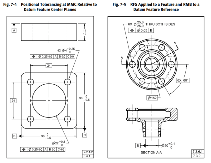
Hole Pattern Position With Central Hole as Datum Drafting Standards
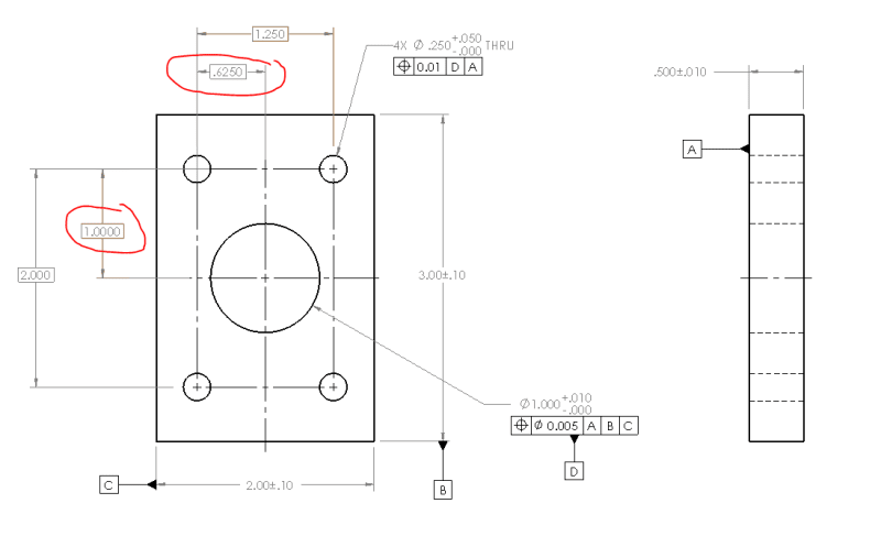
Dimensioning Hole Patterns
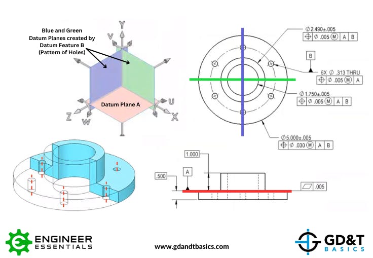
Common GD&T Student Questions A Pattern of Holes as a Datum Feature
Tolerance Of Position Dimensional Consulting
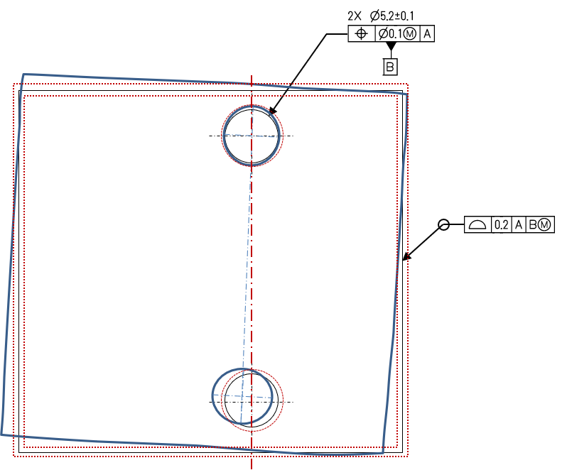
Hole Pattern as a Datum Feature TEStechnologies

Are You Using GD&T Correctly? Geometric Learning Systems

GD&T Tip Datums Watch placement of datum triangles in the latest
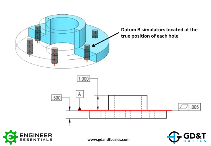
Common GD&T Student Questions A Pattern of Holes as a Datum Feature

Common GD&T Student Questions A Pattern of Holes as a Datum Feature
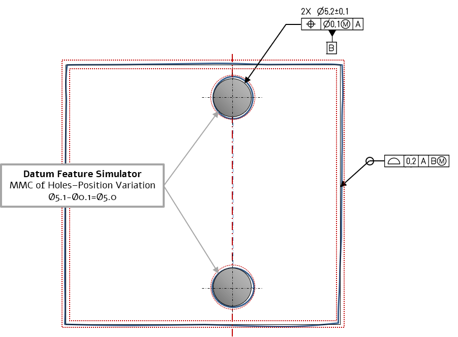
Hole Pattern as a Datum Feature TEStechnologies
In Figure 3, We Observe A Composite Tolerance Created Using Buildit Metrology Software.
Web On The Right, The Pattern Of Four Holes Is A Primary Datum.
Web Yes, You Are Absolutely Allowed To Use A Pattern Of Holes (Or Other Fos) As A Datum.
Web This Situation Comes Up A Lot In Our Parts.
Related Post: