Draw The Shear And Moment Diagram For The Beam
Draw The Shear And Moment Diagram For The Beam - Description of the device 1 is the beam 2 is the load hanger 3 is the shear force load hanger 4 is the bending moment load hanger where: Web shear force and bending moment diagrams are powerful graphical methods that are used to analyze a beam under loading. Draw the shear and moment diagrams for the beam. Internal forces in beams and frames. Write answers in the space provided. Advanced physics questions and answers. Shear and bending moment diagrams. We go through breaking a beam into segments, and then we learn about the relationships between shear force. Mechanical engineering questions and answers. The flexural stress at point section. Start at one end, (point a), of the beam and work toward the other end. Web you will be fully competent in drawing shear force and bending moment diagrams for statically determinate beams and frames. You'll get a detailed solution from a subject matter expert that helps you learn core concepts. (see above) sum up the forces in the vertical. If you’re not in the mood. Web you will be fully competent in drawing shear force and bending moment diagrams for statically determinate beams and frames. On a transverse cross section 1 ft from the left end, determine. Draw the shear and moment diagrams for the beam. The flexural stress at point section. Taking moment about point a. Figures 1 through 32 provide a series of shear and moment diagrams with accompanying formulas for design of beams under various static loading conditions. Web the first step in calculating these quantities and their spatial variation consists of constructing shear and bending moment diagrams, \(v(x)\) and \(m(x)\), which are the internal shearing forces and bending. Draw the shear and moment diagrams for the beam. In each problem, let x be the distance measured from left end of the beam. You'll get a detailed solution from a subject matter expert that helps you learn core concepts. This problem has been solved! Web the equation also suggests that the slope of the moment diagram at a particular. Divide the beam (of length l) into n segments. Without there being any load applied to the beam, check that the beam is in its equilibrium position. Adjust the tension springs if necessary. Internal forces in beams and frames. You will have a robust system of analysis that allows you to confidently tackle the analysis of. Timber beam is loaded as shown in fig. (see above) sum up the forces in the vertical direction. Write answers in the space provided. Equilibrium structures, support reactions, determinacy and stability of beams and frames. Make sure to divide the load correctly) Web shear force and bending moment diagrams are powerful graphical methods that are used to analyze a beam under loading. Divide the beam (of length l) into n segments. Internal forces in beams and frames. Web when designing a beam it is important to locate the points of maximum shear and maximum moment and their magnitudes because that’s where the. As usual, indicate all important values including points of discontinuity, points of change in curvature, and points of extrema on the x and y axes. Mechanical engineering questions and answers. 1) calculate support reactions 2). Web this is an example problem that will show you how to graphically draw a shear and moment diagram for a beam. Also, draw shear. Σ m a = 0 ( 1 2 × 30 × 9) × ( 2 × 9 3) + 180 = r b × 9 r b = 110 ( l b) explanation: Figures 1 through 32 provide a series of shear and moment diagrams with accompanying formulas for design of beams under various static loading conditions. Internal forces in. We go through breaking a beam into segments, and then we learn about the relationships between shear force. Equation 6.1 suggests the following expression: Web this is an example problem that will show you how to graphically draw a shear and moment diagram for a beam. 1) calculate support reactions 2). Determine all the reactions on the beam. Internal forces in plane trusses. 20 kn 40 kn/m cl 150 kn m 8 m 3 m prob. The flexural stress at point section. You'll get a detailed solution from a subject matter expert that helps you learn core concepts. As usual, indicate all important values including points of discontinuity, points of change in curvature, and points of extrema on the x and y axes. (see above) sum up the forces in the vertical direction. Web you will be fully competent in drawing shear force and bending moment diagrams for statically determinate beams and frames. Assume that the flexural rigidity is a multiple of ei and differs for each member as shown in the figure. Draw the shear force, axial force and bending moment diagrams. Figures 1 through 32 provide a series of shear and moment diagrams with accompanying formulas for design of beams under various static loading conditions. X 1 = 0.15m x 2 = 0.10m x 3 = 0.05m a = 0.105m step 1: Shear and bending moment equations. This page will walk you through what shear forces and bending moments are, why they are useful, the procedure for drawing the diagrams and some other keys aspects as well. Internal forces in beams and frames. Description of the device 1 is the beam 2 is the load hanger 3 is the shear force load hanger 4 is the bending moment load hanger where: Determine all the reactions on the beam.
Learn How To Draw Shear Force And Bending Moment Diagrams Engineering
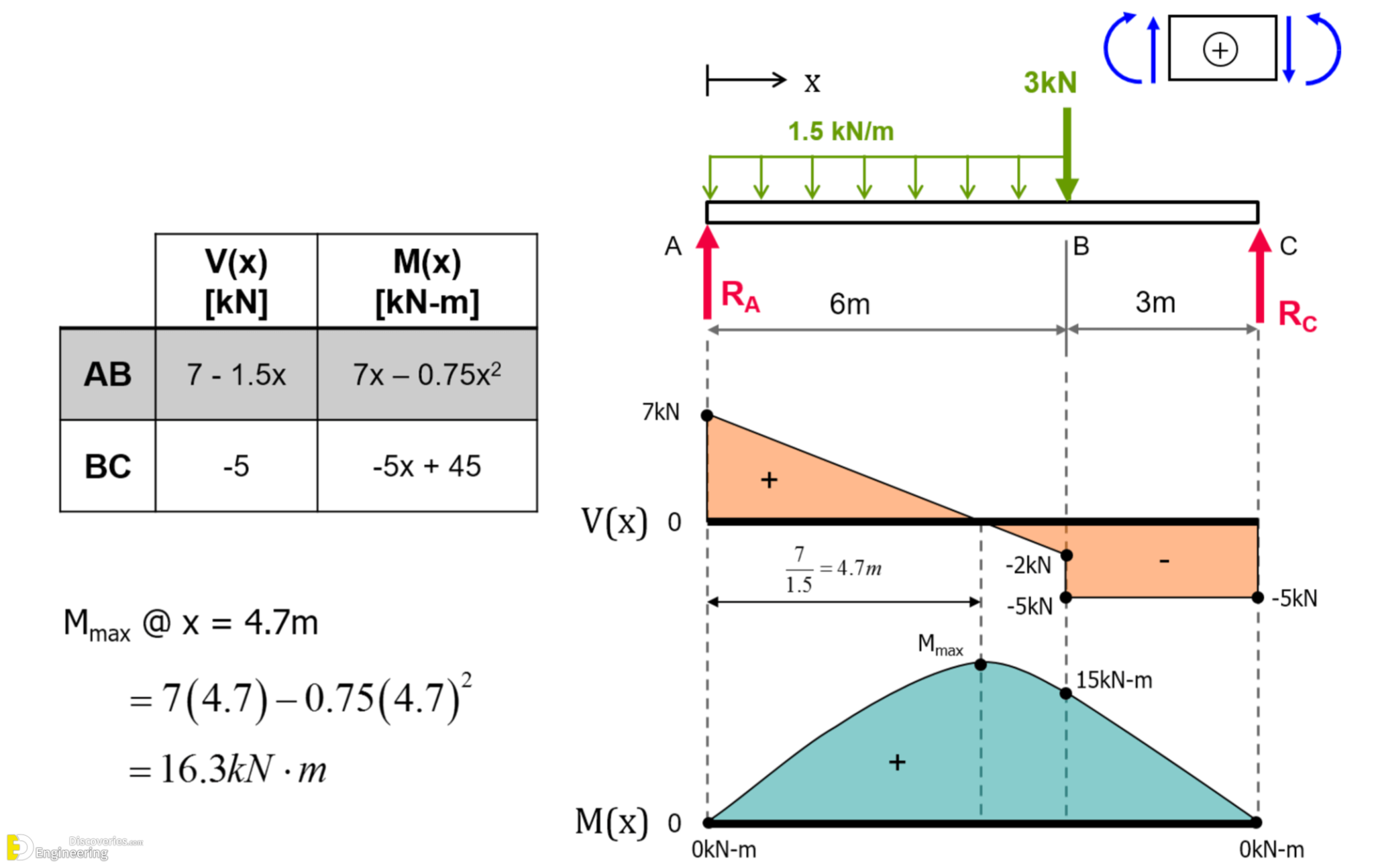
Learn How To Draw Shear Force And Bending Moment Diagrams Engineering
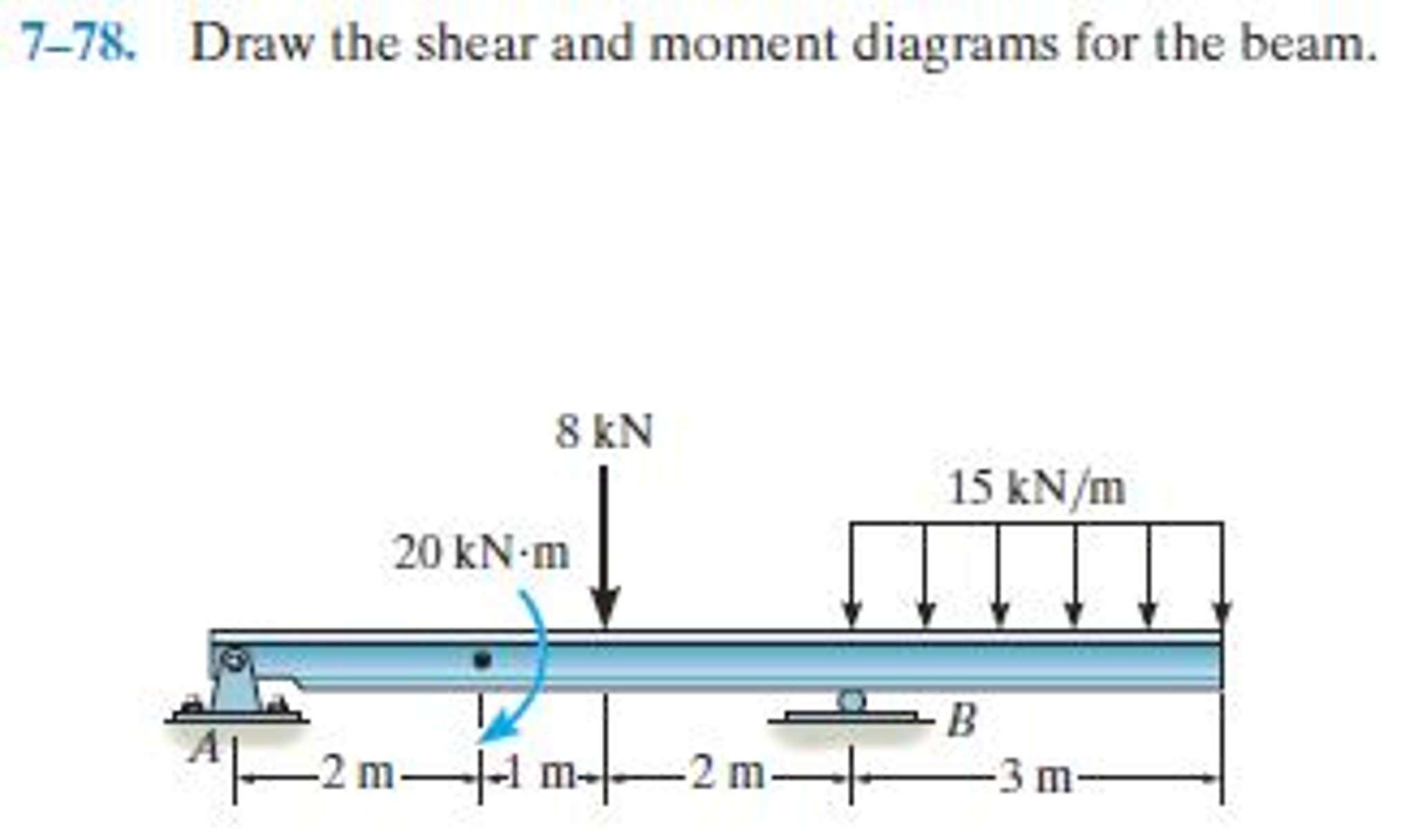
Draw the shear and moment diagrams for the beam.
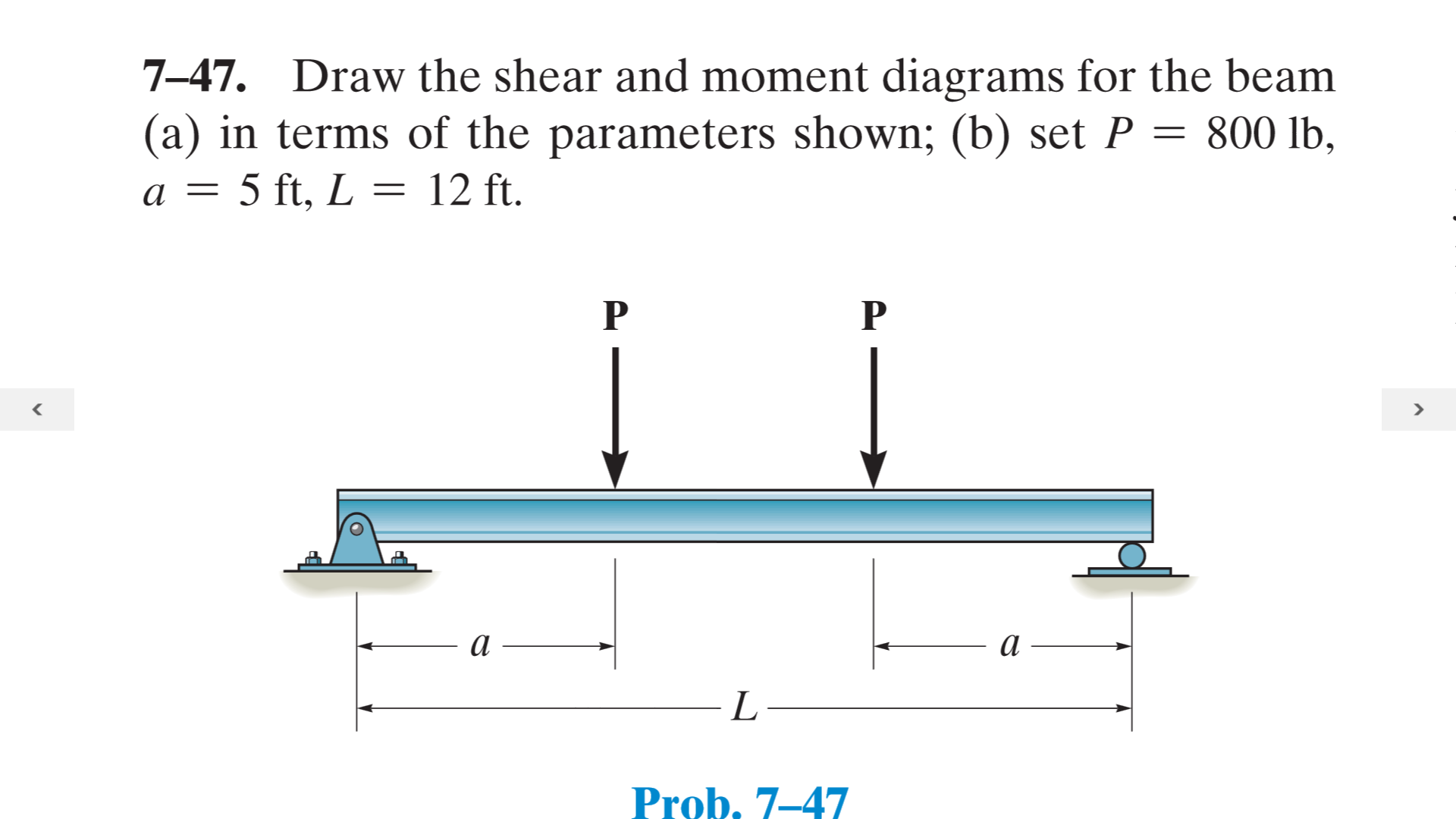
Solved Draw the shear and moment diagrams for the beam (a)

Solved Draw the shear and moment diagrams for the beam
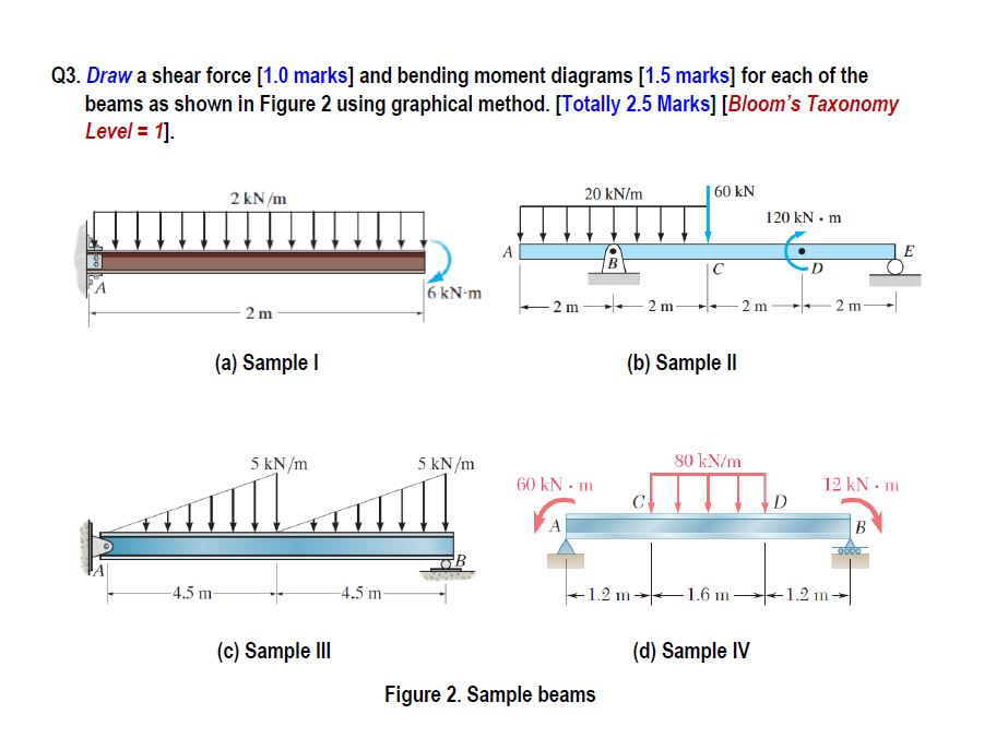
Shear and moment diagrams geekloki

Drawing Shear and Moment Diagrams for Beam YouTube

Statics 7.71 Draw the shear and moment diagram for the beam. YouTube
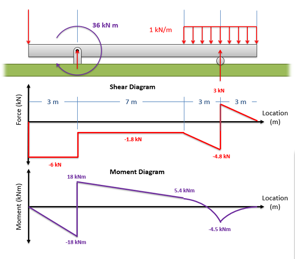
Mechanics Map Shear and Moment Diagrams
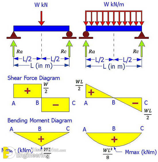
Learn How To Draw Shear Force And Bending Moment Diagrams Engineering
Web When Designing A Beam It Is Important To Locate The Points Of Maximum Shear And Maximum Moment And Their Magnitudes Because That’s Where The Beam Is Most Likely To Fail.
Advanced Physics Questions And Answers.
3 2 5 2 0 2 Kn Mmaa0:
1) Calculate Support Reactions 2).
Related Post: